fms serial

NOT PUBLISHED
Introduction
This is a brief description of the operation of the FMS PIC serial interface, the interface is design to take the buddy box output of PPM mode transmitters from Futaba, JR, Hitec and sanwa etc, and convert this output to an ASCII data string of the format listed below. It will only work with systems which operate over the range 1 - 2mS.
Kit of Parts
Kit Assembly Instructions in MS Word format
Kit Assembly Instructions in Adobe PDF format
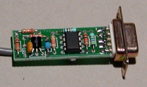
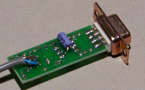
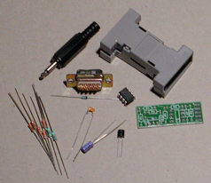
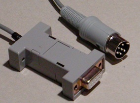
There is now a kit of parts available for the interface, shown below are some pictures of the finished interface showing the top and bottom of the finished board, the finished interface in it's case and the kit of parts. When ordering a kit please make sure to state what type of buddy box plug you require.
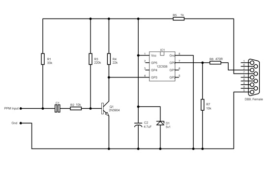
Circuit Diagram
Use with FMS 2.0 Beta 7
From the 'Controls' menu select 'Analogue control'. From the Interfaces option select 'Serial PIC interface' and then click 'Resources' select the Com port you are using and then for the Protocol make sure you have '9600 Baud / 0xF0+ Sync' selected.
Serial Protocol Used
The serial output is at 9600 baud, 8 data bits, No parity and 1 stop bit. The first character will be in the range 241 to 248 decimal, this is made up from 240 + the number of pulses measured. The second character contains the status of 4 push buttons that can be connected to the interface unit. The third to last (max 16) characters contain the values of the control channel pulses. Decimal 100 = 1mS, 200 = 2mS.